A few weeks ago Jane Street posted a puzzle that I could not stop thinking about. They designed a custom chip, ran it through a real physical design flow, and published only the final GDSII layout file. No source, no netlist, no documentation. The layout is the manufacturing output, the last artifact in the chain, and it is nothing but coordinates and polygons. Your job is to work backwards from geometry to logic, figure out what the chip computes, and then use that understanding to make an output pin called success go high.
I had never opened a GDS file before this. What follows is how I got from 1.4 megabytes of rectangles to the string the chip was hiding, and why the most valuable file in the whole repository turned out to be the one labelled as a warm-up exercise.
The Warm-Up Is the Real Gift
The repository ships a small example design alongside the puzzle: two shift registers, an adder, and a comparator that raises a flag when A plus B equals 496. Crucially, it ships that design at every stage of the flow. The original Verilog, the synthesized gate-level netlist, the post-place-and-route floorplan, and the final GDS.
It is tempting to skim past this and go straight for the interesting file. That would be a mistake, and avoiding it is the single most important thing I did right. The warm-up is the only place in the entire puzzle where you have ground truth. If your extractor can turn the warm-up GDS back into something that provably computes A plus B equals 496, you can trust it on the real chip. If it cannot, you will spend hours staring at logic that makes no sense, unable to tell whether the design is clever or your tooling is broken.
So I made a rule for myself. Do not open the puzzle file until the warm-up round-trips.
The GDS Kept Its Cell Names
First thing I did was dump the cell hierarchy. Eighty-one cell definitions, one top-level cell named puzzle, and then this:
The standard cells kept their names. And not just their names. Dumping the labels inside one of them gives you A, B, Y, VPWR and VGND sitting on the li1 label layer, exactly where the physical pins are. The README says many internal names were removed, and what actually got removed was the top-level net names. The cell library is completely intact.
That changes the problem enormously. I do not have to identify gates from transistor geometry, which would have been a genuinely hard, computer-vision-shaped problem. I know what every cell is and where each of its pins sits. All I have to determine is which pins are electrically connected to which. That is a connectivity extraction, and connectivity extraction is tedious but entirely mechanical.
Two more things I checked before writing any real code, because getting either wrong would have cost me hours of confusion later. First, every cell placement uses magnification one, a rotation of only zero or 180 degrees, an optional Y-mirror, and no array repetitions, so the coordinate transform is four lines of code. Second, every polygon in the top-level cell has exactly four vertices. All 1499 of them. The router emitted nothing but rectangles.
Turning Rectangles Into Nets
With that established, the extractor came to about 120 lines of Python. It works in five stages.
• Decompose into rectangles: all the geometry is Manhattan, so a scanline band decomposition is exact. Collect the distinct Y coordinates of every vertical edge, and for each horizontal band, sort the vertical edges crossing that band and pair them off even-odd. Rectangles go in, rectangles come out, and the L-shapes inside the standard cells come out as a few stacked rectangles. Layout path records get converted to polygons first.
• Flatten the hierarchy: walk the top cell's references and transform each cell's local rectangles into absolute nanometre coordinates.
• Merge each layer: union-find over rectangles that touch or overlap on the same layer, using closed intervals so that shapes sharing only an edge still count as connected. Everything gets bucketed into a two micrometre grid first, so this is not ninety-two thousand squared comparisons.
• Stitch the layers together: for every via shape, find the metal it overlaps on the layer below and on the layer above, and union all of it into one net. The via layers climb from the local interconnect up through the fifth metal layer.
• Attach the names: transform each instance's pin labels into absolute coordinates and look up which net contains that point. The same trick on the top-level labels recovers clk, rst_n, enable, the serial input, success, and the eight output bits.
The single number I watched most closely while debugging was the count of unconnected vias. A via that does not land on metal on both sides means my layer map is wrong, or my decomposition dropped a shape, or I fumbled a transform. It went from several hundred down to zero as I fixed things, and the moment it hit zero, everything else clicked into place.
Zero unconnected vias means I did not miss any connections. Zero pins resolving to more than one net means I did not invent any.
For gate behaviour, I did not want to rely on remembering what a cell named a21boi does. SkyWater publishes functional Verilog for every cell in the library, and it is all structural primitives, so I wrote a small parser that turns those files into primitive gate lists. The semantics are the vendor's, not my recollection of them.
Then the test I had been building towards. Extract the warm-up GDS, levelize the combinational logic, simulate eight clock cycles of shifting followed by the comparison, and check the output flag against A plus B equals 496 on three hundred random pairs. All three hundred matched. Now I could open the puzzle.
Ninety-Two Flip-Flops
The real chip came out to 942 cells and 1794 primitive gates. The success pin traces straight back to a single flip-flop through one buffer, so the entire question becomes: what sets that flop?
Reading 1794 gates by hand was not appealing. Instead, for each flip-flop I computed the set of other flip-flops appearing in its data input's combinational support, and printed the result sorted by physical position on the die. The structure jumps straight out:
Flops 44 through 48 depend only on themselves and enable. That is a counter. Flops 73 through 76 do the same thing but gated by the first group, so that is a second counter ticking when the first one wraps. Then there is a long list of flops that come in pairs, where 12 depends on 12 and 20, and 20 depends on 12 and 20. And finally a set of flops with roughly 385-gate input cones that all reference the second counter.
Expanding the success flop's input into a boolean expression was the moment the shape of the thing appeared:
Twenty-two two-flop pairs, each of which has to end up holding one specific two-bit value. Two sticky flags that must stay clear. And eight flops that have to hold one exact pattern. Simulating the counters told me enable is held high for exactly 121 cycles, and 121 is eleven times eleven. Eleven pairs in one group, eleven in the other.
At that point I was confident it was a grid constraint puzzle with per-row and per-column counts, and I guessed N-queens. I was wrong, but not by much.
The Chip Tells You What It Is
Before chasing that theory, I ran the simplest possible input through my simulator, all zeros, purely to see what the output block would do. Eight bits clocked out, one character per cycle:
That was a genuinely good moment, for two separate reasons. The obvious one is that it is a hint about the domain. The better one is that nine bytes of clean English do not fall out of a netlist you reconstructed incorrectly. It was end-to-end confirmation that my rectangles, my vias, my pin mapping, my parsed cell models and my simulator were all correct simultaneously.
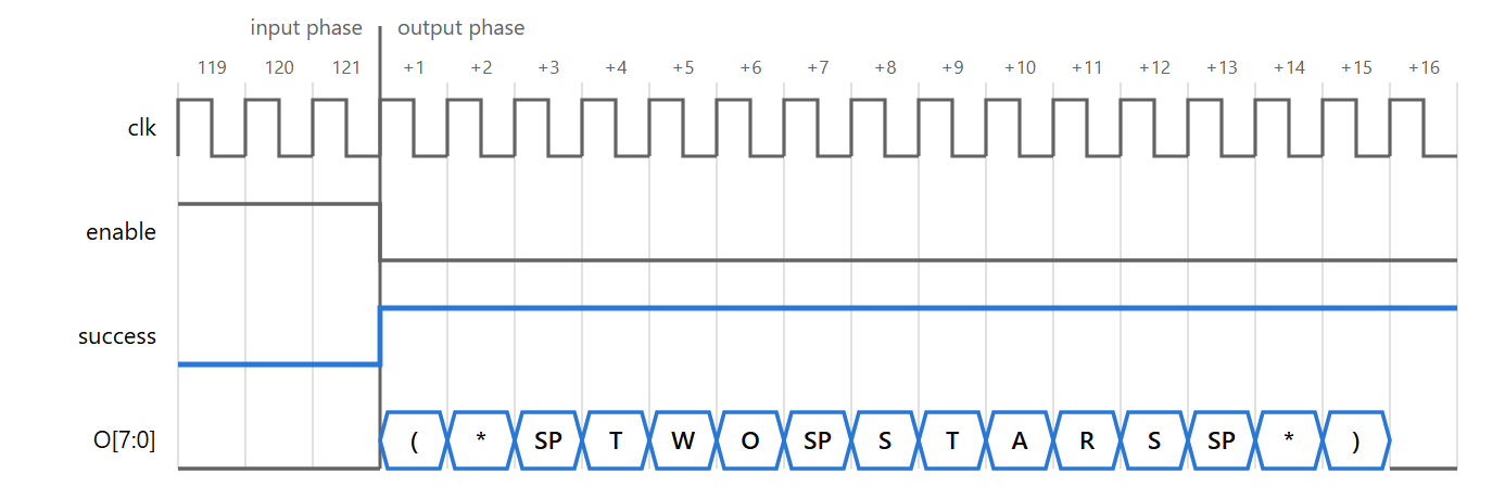
I had also noticed by then that the provided example waveform makes the chip spell TRY AGAIN, so the output block clearly holds more than one message.
So I went back to the flop pairs and probed them. Place a single one-bit at grid cell row r, column c, and record which pair's accumulator moves. The second group of eleven pairs turned out to depend only on the column, so those are column counters. But the value they have to reach works out to two, not one, which killed the N-queens theory. The confirmation arrived when I fed a candidate solution in and the chip printed a string that named the game outright:
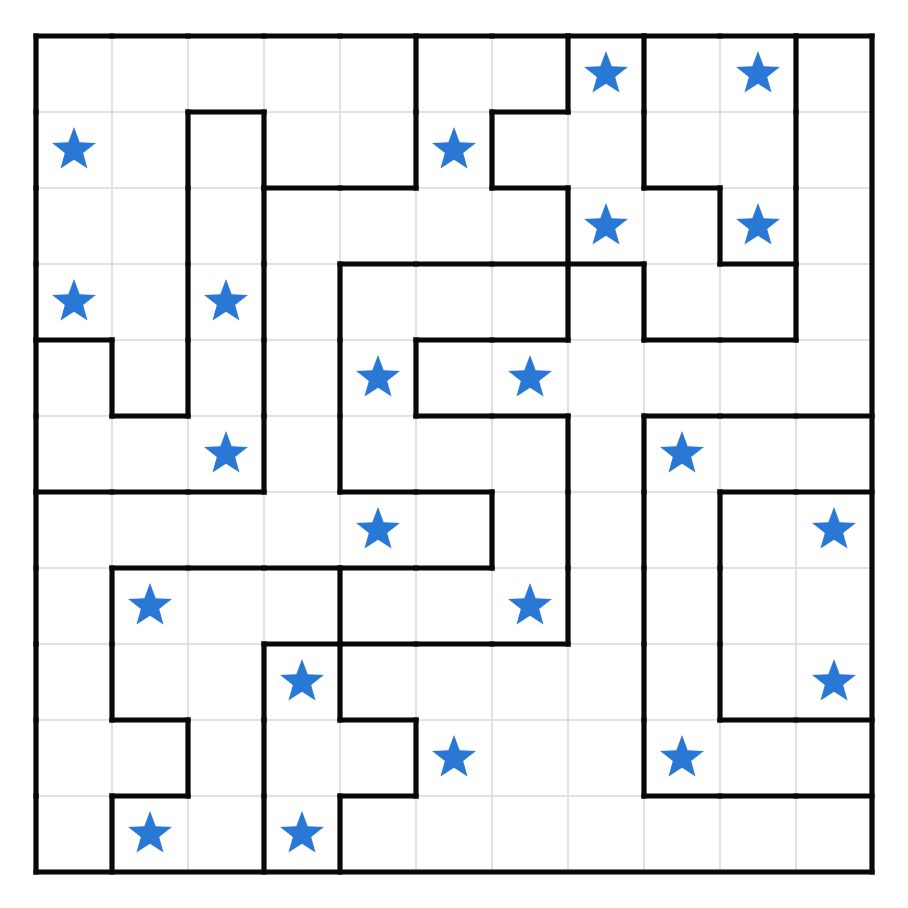
Two stars per row, two per column, and a no-touching rule that had been sitting in front of me the entire time in the form of a twelve-stage shift register. It is a Star Battle, also known as Two Not Touching.
What Every Block Does
Once you know the game, every block on the die has an obvious job. Two counters supply the coordinates: one counts zero to ten and wraps, giving the column, and the second ticks on each wrap, giving the row. A sticky flag marks the end of the input phase after the 121st bit. Neither counter depends on the input at all, which becomes important later.
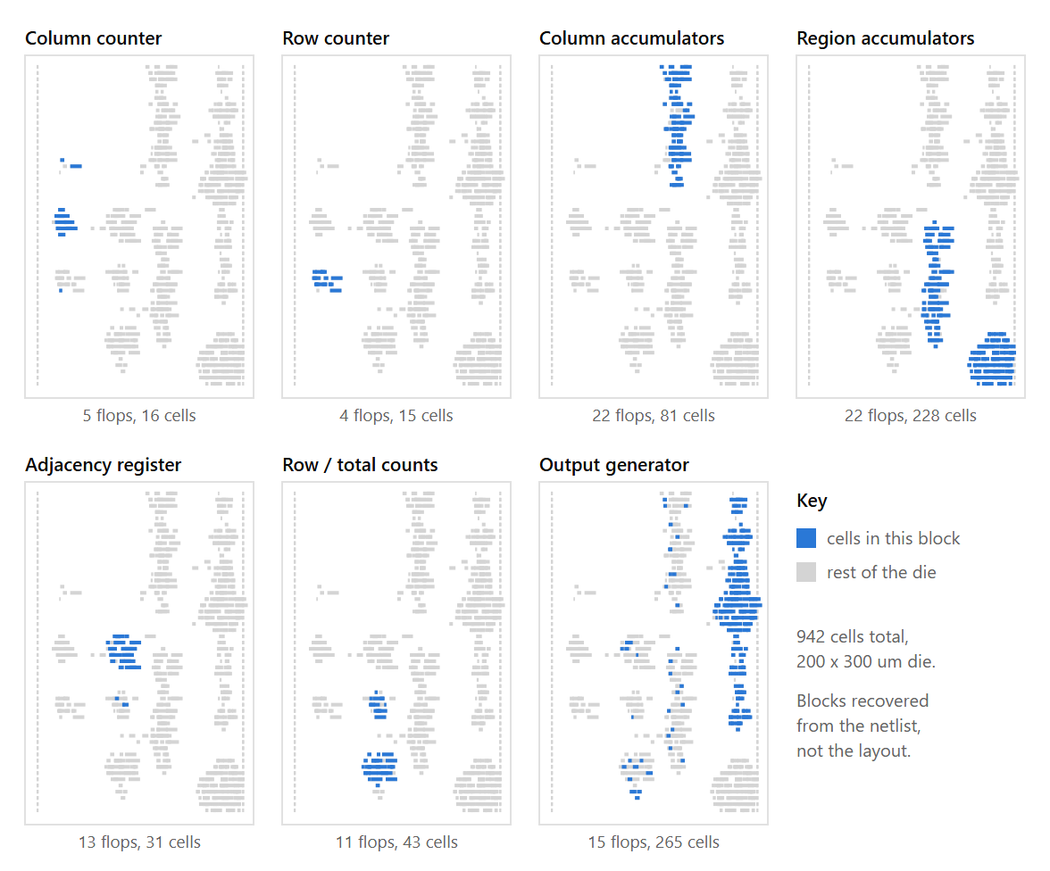
Eleven two-bit accumulators count stars per column, each enabled when the column counter matches its index. Eleven more count stars per region, and these are the flops with the enormous 385-gate input cones, because their enable has to decode which region a cell belongs to from the row and the column together. A single two-bit counter with a sticky error flag handles the row count, checked at the end of every row. And an eight-bit ripple counter tracks the total, which has to read exactly twenty-two.
The adjacency check is the prettiest part of the design. A twelve-stage shift register holds the last twelve input bits, and because a row is eleven cells wide, the taps land on exactly the neighbours you care about:
The counter terms are just edge-of-row guards, so that column zero does not wrap around and compare itself against column ten of the previous row. And checking only the four already-seen neighbours is enough by symmetry: every adjacent pair gets caught exactly once, when the later of the two arrives. That is the entire no-touching rule, diagonals included, in about a dozen gates plus a shift register. I found this genuinely lovely.
Reading the Puzzle Off the Silicon
The region map is not stored anywhere as data. It is baked into the decode logic feeding those eleven region accumulators. Rather than untangle 385 gates eleven times over, I probed for it. Place exactly one star at each of the 121 cells in turn and record which accumulator moves. That is 121 simulations, and out comes the map.
Here is the recovered puzzle:
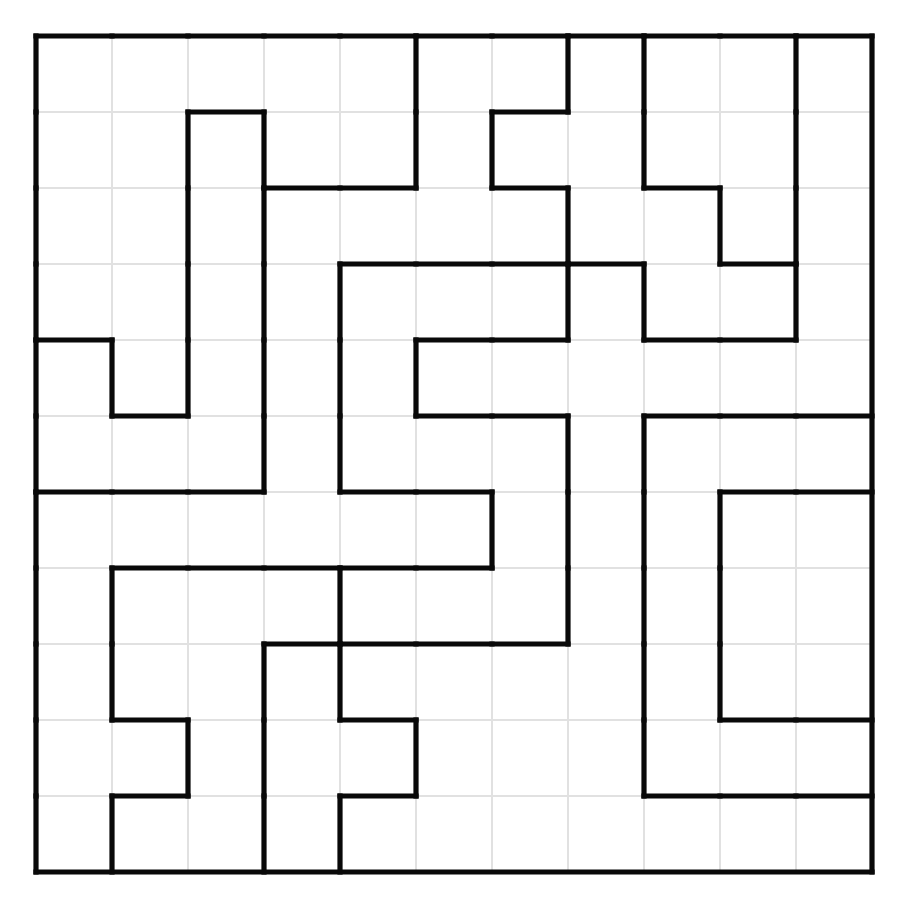
Every region is orthogonally connected, which I checked. The sizes come out to 4, 5, 6, 7, 8, 8, 9, 11, 14, 21 and 28, which is far more irregular than a typical hand-made Star Battle. But the puzzle is well formed and the solution is unique, so it does its job.
Letting a SAT Solver Do the Puzzle
I want to be honest about this. I never solved the Star Battle by hand. Once you hold a gate-level netlist, you do not need to understand the puzzle to solve it. You compile the circuit into a boolean formula and ask a solver for an input that makes success true.
The thing that makes this cheap is that the counters do not depend on the input. I verified that by simulating the counter trajectory with all zeros, all ones and a random input, then asserting all three traces are identical. That means I can constant-fold both counters and every phase signal at every cycle, which strips a large amount of logic out of the unrolled formula before the solver ever sees it.
After that it is a textbook bounded unrolling. The success cone is 68 flops and 897 gates per cycle. Unroll 121 cycles with a Tseitin encoding, initialize every flop to zero since they all have resets, tie enable and reset high, leave the serial input free, and assert the final condition.
It solved instantly. Then I added a blocking clause and asked again, and it came back unsatisfiable. The solution is unique, which matters more than it sounds like, because of the next part.
The Detail I Liked Most
The output block is an eight-bit nonlinear state register plus a four-bit character counter, and the output bus is a four-way select. I found the selector conditions by expanding one output bit symbolically and noticing that the multiplexer terms decode the total star counter being zero and being 121.
• Zero stars: the chip prints EMPTY SKY.
• All 121 stars, every cell filled: it prints BIG BANG.
• Success high: it prints the answer.
• Anything else: it prints TRY AGAIN.
The three easter-egg branches are plain read-only memory. The winning branch is that memory exclusive-ORed with the eight-bit state register, and that register spends the entire input phase absorbing your input bits. It is a tiny keystream derived from what you shifted in.
I tested this by holding the input fixed and scrambling those eight flops, and the answer came out as fifteen bytes of noise. Which is exactly the point. You cannot force success high, or patch the netlist, or guess at the string. If the 121 bits you shifted in are not precisely right, the keystream is wrong and the message decodes to garbage. The only way to read the answer off the chip is to genuinely solve the puzzle. I appreciated that more the longer I looked at it.
Easter Eggs
There are at least six hidden in the puzzle.
• EMPTY SKY: feed the chip an all-zero grid.
• BIG BANG: feed it an all-ones grid, every one of the 121 cells. These two, plus the default TRY AGAIN and the winning message, are the four branches of the output mux, selected by the total-star counter and the success flag.
• The night sky awaits: hidden inside the example waveform file. Its 242 stimulus bits are two 121-bit attempts. Take each grid row's first seven bits as an LSB-first seven-bit ASCII character, and the twenty-two rows spell out the sentence. It is also why columns seven through ten sit conspicuously empty in that stimulus, which is what made me look in the first place.
• The waveform file's version field: Leave no stone unturned. But for this file, consider looking at it in a waveform viewer instead.
• Its date field: Sat Dec 31 23:59:60 2016. Second sixty. That was a real leap second.
• The answer string: it is itself an OCaml comment, which is a nice touch for Jane Street.
I also went hunting for hidden geometry in the layout itself and found nothing. Every top-level polygon is a plain four-vertex rectangle, the only non-routing layers are the place-and-route boundary and some filler cells whose names were stripped, and there is no text drawn in metal.
Final Thoughts
The whole thing is Python. gdstk for parsing the layout, python-sat for the solve, and SkyWater's own functional Verilog for cell semantics. No commercial tools, no layout-versus-schematic flow, no dedicated extraction engine.
If you attempt something like this, spend your first hour on the warm-up rather than the puzzle. Extraction is the kind of task where being ninety-nine percent right feels completely identical to being one hundred percent right, right up until it suddenly does not, and the warm-up is the only place where you can tell the difference. Every hour I spent making A plus B equals 496 come back out of a GDS file paid for itself later, because after that I never had to wonder whether some strange-looking piece of logic was a deliberate design decision or a bug in my own extractor.
When EMPTY SKY scrolled past on an eight-bit bus I had reconstructed from nothing but rectangles and vias, I knew it was the chip talking and not me. That is the part I will remember.
The full writeup, the extraction pipeline and the recovered puzzle are on GitHub: https://github.com/shaikhmubin02/asic-puzzle-2026-solution